
Ethernet cables seem like the most basic devices in your home network. They’re cables that you connect to the devices in your office or home, and they give you a connection to the network.
On top of that, they all look alike (although they might be different colors).
Just when you let your guard down and get overconfident about them, you learn that there’s way more to them than you first thought.
For example, you might be surprised to hear:
- There are different types of cables that are identified by a cat number
- If you choose the wrong type of cable, it can slow your internet connection
- Not every type of ethernet cable is compatible with the other types
And that’s just scratching the surface.
Another ethernet cable term that may have caught you off guard is pinout standards.
What exactly does this term mean, and how does it apply to ethernet cables?
Hopefully I can help sort this out for you.
Ethernet cable pinout standards detail the order of wires inside an ethernet cable’s connectors. This standardization ensures that ethernet cables and devices they connect to are all compatible with each other.
In this post, I’ll detail all you need to know about ethernet cable pinout standards. I’ll also answer some frequently asked questions about them.
Where did ethernet cable pinout standards come from?
Ok, so we’ve established that pinout standards establish how ethernet cables are wired.
There are a few natural follow up questions to this.
Firstly, who said these are the standards that should be followed when making cables? And why were they chosen to make the rules?
Truth be told, the cable pinout standards came from a collaborative effort.
The name of the standard that details how ethernet cables should be wired is called ANSI/TIA-568.
This standard was published by the Telecommunications Industry Association, which is where the “TIA” in the standard comes from. The “ANSI” stands for the American National Standards Institute, which is the group that signed off on the standard that TIA put forth.
These groups may not sound like a big deal, but they actually carry a lot of weight in developing different standards for industry.
After all, the whole purpose of ANSI is to develop standards in a wide variety of areas.
For the ANSI/TIA-568 standard, more than 60 groups worked together to come up with it. These groups consisted of different industries and professions (e.g. consultants, telecommunications companies, banks, etc.). Developing it with so many people involved ensured that everyone was on the same page.
With so many influential companies involved in the creation of the standard, it’s no surprise that it was widely adopted.
Why are pinout configurations needed in the first place?
Now that we’re done paying our respects to those who developed the standard, let’s dig a bit deeper.
Why are ethernet cable pinout standards needed in the first place?
That’s because when it comes to ethernet cables, communication is extremely important (pun intended).
The reason this standard is so important is because there’s actually quite a lot going on inside an ethernet cable.
Inside an ethernet cable, there are 8 copper wires. Each wire is assigned a different color for identification purposes.
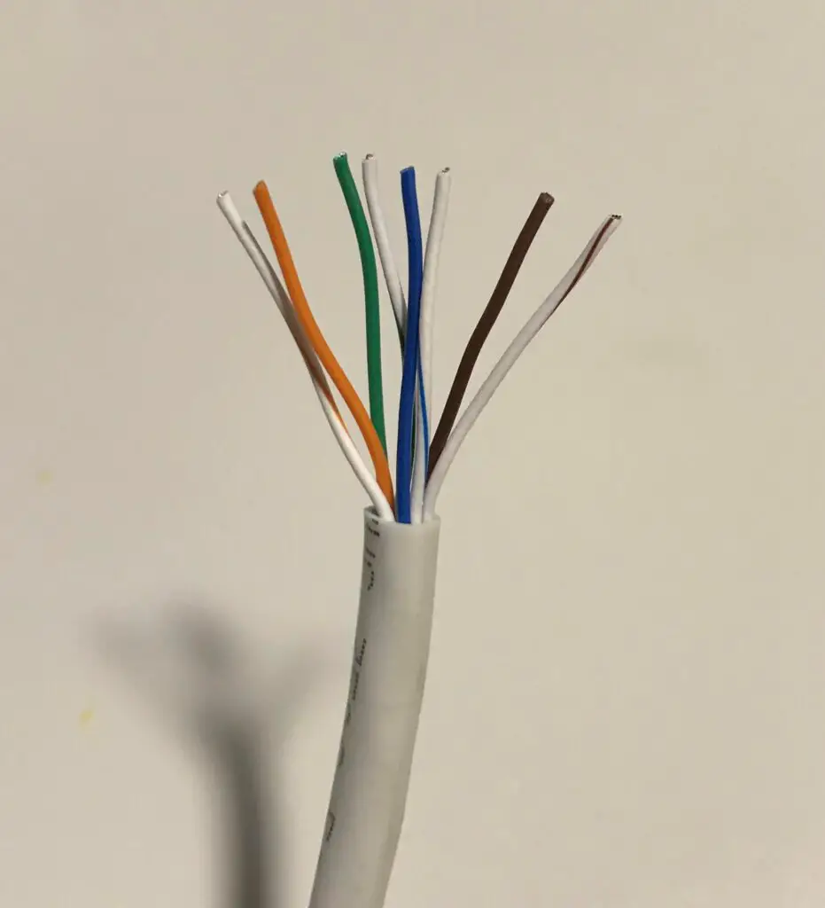
These wires are used to move data back and forth between both ends of the cable. The data is moved using pulses of electricity through the wires.
Some of these wires are meant to send data, while others are meant to receive data. There are even some wires that don’t have any job at all.
The best way to think of this is a highway.
You have some cars traveling in one direction, while other cars are traveling in the other direction. If you don’t have a standard in place that explains which lanes are used for each direction, you’re setting yourself up for disaster.
Taking this analogy a step further, imagine if each town or city had different rules in place regarding which lane to drive in depending upon the direction you were going in.
Not a pretty picture, is it?
This is where the ANSI/TIA-568 standard is so helpful. It helps identify which wires are meant to send data to the other side of the cable, and which are used to receive data from the other side.
With all cable and device manufacturers following the same standard, it ensures everyone is using the same rules of the road. This makes data travel easier for all parties involved.
What are the pinout configurations?
As I mentioned earlier, inside an ethernet cable each wire has a specific role. The role of each wire is determined by its position inside the RJ45 connector at the end of it.
For those of you that may not be familiar, these are the 8 wires of an ethernet cable inside an RJ45 connector:
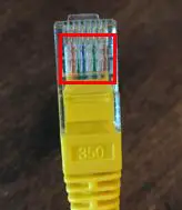
As you can see, the 8 wires are side-by-side in the RJ45 connector. The fact that each of these wires is a different color makes things much easier.
So how do you know what order the colors go in?
These positions are defined in the ANSI/TIA-568 standard.
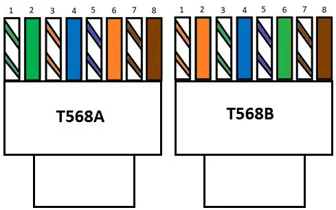
The standard provides two different pinout configurations that can be used inside an RJ45 connector. These pinouts are called T568A and T568B.
T568A pinout configuration
Here’s what the T568A pinout configuration looks like (when the tab of the RJ45 connector is facing away from you):
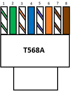
With a T568A wiring configuration, the wires are in the following order from left to right:
- White with a green stripe
- Green
- White with an orange stripe
- Blue
- White with a blue stripe
- Orange
- White with a brown stripe
- Brown
T568B pinout configuration
Here’s what the T568B pinout configuration looks like (again with the RJ45 connector tab facing away from you):
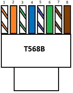
In a T568B pinout configuration, the wires are in the following order from left to right:
- White with an orange stripe
- Orange
- White with a green stripe
- Blue
- White with a blue stripe
- Green
- White with a brown stripe
- Brown
To make it easier to see, here’s what a T568B pinout configuration looks like before it goes inside an RJ45 connector:
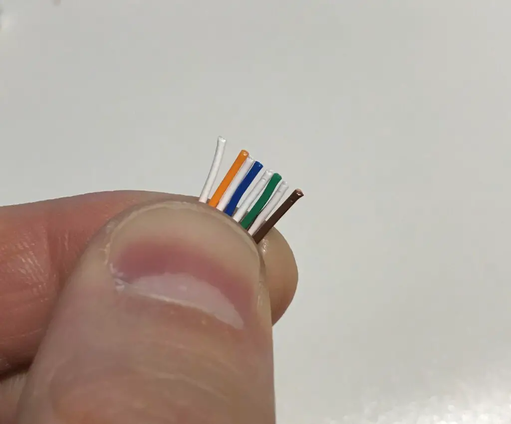
Please note that although you can’t see them, the white wires have colored stripes on them. They’re not all white. You have to trust me on this one.
Ok, there you have it.
Those are the two standards for wiring your ethernet cables. As long as the wires follow one of the two configurations, your cable should work just fine.
What is the difference between the T568A and T568B configurations?
To identify the differences between the T568A and T568B configurations, let’s take a closer look at the order of the wires in each case.
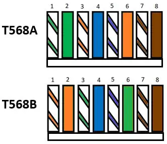
At first glance, it might look like these configurations are quite different.
In reality, the only difference between the two is that the green and orange wires are switched in the two different configurations. This includes the striped wires for these colors as well.
In other words, if you take every orange wire in a T568A configuration and replace it with a green wire of the same type (solid or striped) and vice versa, you’d get a T568B configuration.
So why is there more than one way to configure the wires in the first place?
That’s a good question. Let’s dive into it.
Why are there two different pinout configurations?
Let me start by saying that when ethernet cable pinout standards were developed, we were in a different age of computers.
Over the years, things have been simplified when it comes to your ethernet cables.
The reason there are two different pinout configurations has to do with the fact that you used to need different cables to connect different types of devices.
For example, if you were using your ethernet cable to connect two computers, it would need to be wired one way. If you were using an ethernet cable to connect your computer and a router, it would need to be wired a different way.
Long story short, this led to the development of two different types of ethernet cables.
The cables used to connect two different types of devices (e.g. a computer and an ethernet switch) were called straight through cables, while the cables used to connect two of the same type of device (e.g. two computers) were called crossover cables.
The details about these cables are less important in this discussion, but it explains why two different pinout configurations exist.
The bottom line here is that ethernet cables needed to be wired differently based upon the devices they were connecting.
With that said, you no longer need to worry about what ethernet cable you’re using when connecting two devices.
Due to advancements in technology, our devices are smart enough to recognize the type of device they’re connecting to. As long as the ethernet cable is wired to either of the standard pinout configurations, you won’t have any problems.
Can you use T568A and T568B configurations in the same cable?
For those of you that decide to make your own ethernet cables, there’s a common question I’ve seen that we should cover here.
As we’ve discussed, an ethernet cable will function properly as long as the ethernet cable is using one of the two standard pinout configurations.
But would the cable still work if you used one pinout configuration for one end of the cable and the other pinout configuration for the other end?
In other words, what if one end of the cable had a T568A configuration and the other had a T568B configuration. Would a cable that looked like this still work?
You bet it would.
This is actually the configuration of a crossover cable that I mentioned in the previous section.
In fact, if you’re making your own ethernet cables you could use any of the following combinations of pinout configurations:
- T568A and T568A
- T568A and T568B
- T568B and T568B
Hopefully you get the picture here.
This hammers home the point that any combination of standard pinout configurations will work fine with your ethernet cables.
Should I use T568A or T568B?
With several different combinations of pinout configurations to choose from in your ethernet cables, it begs the question: is there one pinout configuration that’s better than the others? Will one pinout configuration provide better performance than the others?
The simple truth is it doesn’t matter. You won’t get better performance out of your cable by choosing one pinout configuration over another.
With that said, you’ll find that many of the cat5e and cat6 ethernet cables you can buy online will have a T568B configuration.
In changing the lengths of some of the ethernet cables in my network, I found all of them to have T568B configurations.
Again, it doesn’t make any difference which one you choose. Just know that if you pick T568B configurations you’ll be going with the majority.
Ultimately the choice is yours.
You can be a rebel and use the T568A configuration, or you can follow the popular choice and go with a T568B configuration.
Wrap up
That just about covers ethernet cable wire pinout configurations.
If you have any questions about ethernet cable pinout configurations, or you’d like to share your experiences with ethernet cable pinout configurations, I invite you to drop a line below.
If you’re interested in learning more about similar topics, check out these other posts I’ve written:
Are Ethernet Cables Backwards Compatible?
Do the Colors of Ethernet Cables Matter?
How Do You Crimp Ethernet Cables?
Leave a Reply